In this post showing you how to control Lights, Outlets … etc with google assistant (Google Home, mobile phone app and the new one has Google Assistant built in) .
I’ll my ESP8266 Dev board turning the Relays on my Relay Board on and off, but this could be used to control different things also we can replace ESP8266 with Arduino Or Raspberry pi.
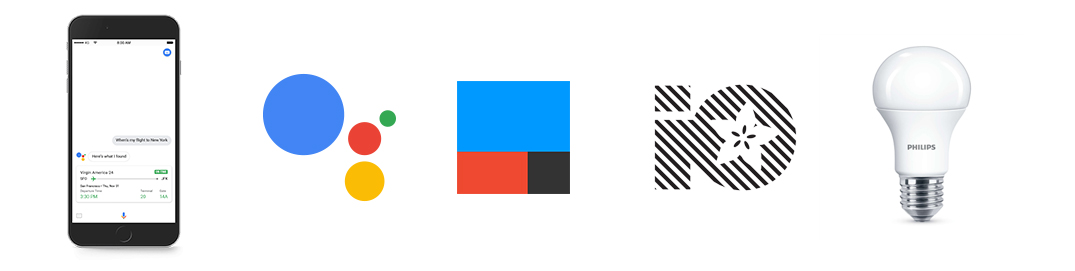
Simply we will use google Assistant through Mobile or Google home to send HTTP requests for Google Assistant everything is a service so Google is partnering with different providers to include options for their services on Google Assistant. One of such partners is IFTTT (IF This Then That) which means you can create custom behaviour responding to your voice commands. That’s pretty cool and IFTTT has already a ton of different options. One of this options is Adafruit IO and WebHooks, which provides an API to perform requests to Adafruit IO feeds then to your ESP8266.
Mainly this is the sequence will be used
- You speak your command
- Google voice services transcript it and search the different providers for one that can handle it, including IFTTT
- IFTTT grabs the command and tells GA “yeah, I can do that”
- IFTTT translates it again based on an applet you have defined
- The action in your applet instructs IFTTT to tell Adafruit IO to do a request
- Adafruit IO performs the request to an address that points to your device
- Your device executes the action
Materials and Accounts required
to make this project you will need to have
- ESP8266 Board https://bit.ly/2scJDVE
- Relay Module https://bit.ly/2sdIxIo
- IFFT Account https://ifttt.com/
- Adafruit IO Account https://io.adafruit.com/
- Computer with internet Connection
Libraries used
- ESP support for Arduino https://github.com/esp8266/Arduino
- Adafruit MQTT library https://github.com/sobhydo/Adafruit_MQTT_Library i’m using Ver. 0.17
Arduino Codes
Github : https://github.com/sobhydo/AoG-Demo
Setup:
Before starting, you should set up the Arduino IDE to program the ESP8266. There are already a ton of tutorials for this, so I won’t repeat all the steps here. This is the one I used to set up my IDE.
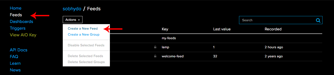
1- Creating Adafruit IO Account, Dashboard and feeds
Adafruit IO is an IOT platform built around the Message Queue Telemetry Transport (MQTT) Protocol. MQTT is a lightweight protocol that allows multiple devices to connect to a shared server, called the MQTT Broker, and subscribe or write to user defined topics. When a device is subscribed to a topic, the broker will send it a notification whenever that topic changes. MQTT is best suited for applications with low data rates, strict power constraints, or slow Internet connections.
In addition to providing the MQTT Broker service, Adafruit IO also allows you to set up dashboards that let you directly manipulate or view the current value of each topic. Since it can be accessed from a web browser, it makes it the ideal hub for monitoring and controlling all of your various IOT projects.

create your Adafruit IO account after that you should be taken to the home screen. Select “Feeds” from the left-hand menu. Click the Actions drop-down menu, and create a new feed. I called mine “Lamp”.
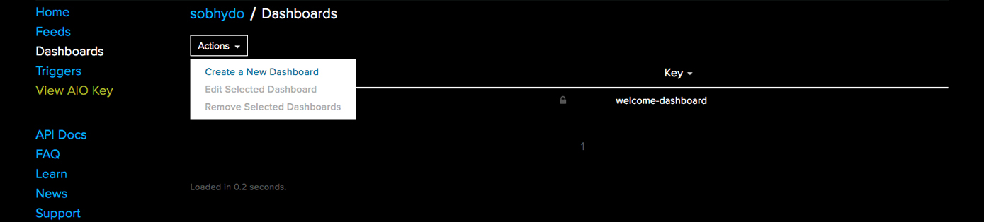
Next, go to Dashboards in the left-hand menu. Click the Actions drop-down menu, and create a new dashboard. I called mine “My Room”.
Open the new dashboard, and you should be taken to a mostly blank page.
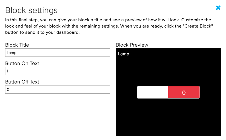
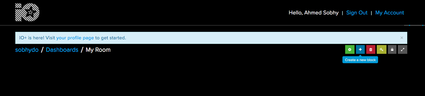 Pressing the blue + button will let you add new UI components to the dashboard. For now, all we’ll need is a toggle button, which should the first option.
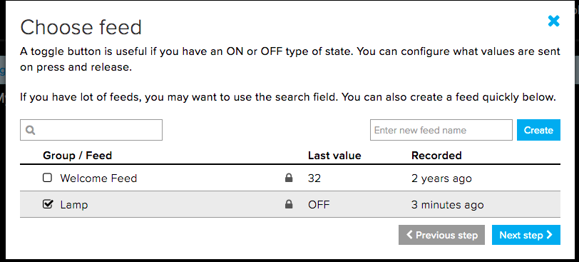
When prompted to choose a feed, select the one you just made, and keep the settings of button as following.
That’s all for now on the Adafruit IO end of things. Next step is connecting your ESP8266 to the MQTT Broker.
2- Connecting the ESP8266 to Adafruit IO
Connecting the ESP8266 to the Adafruit IO system is relatively straightforward. Before you get started with the code, you’ll need to install the Adafruit MQTT Client library, which can be found under the Arduino Library Manager (Sketch > Include Library > Library Manager…).
OR https://github.com/sobhydo/Adafruit_MQTT_Library
There are three libraries you’ll want to include at the start of your program:
#include <ESP8266WiFi.h>
#include "Adafruit_MQTT.h"
#include "Adafruit_MQTT_Client.h"
The first library controls the ESP8266’s wifi connections, and the other two control connections to the MQTT server.
You’ll also want to #define several strings:
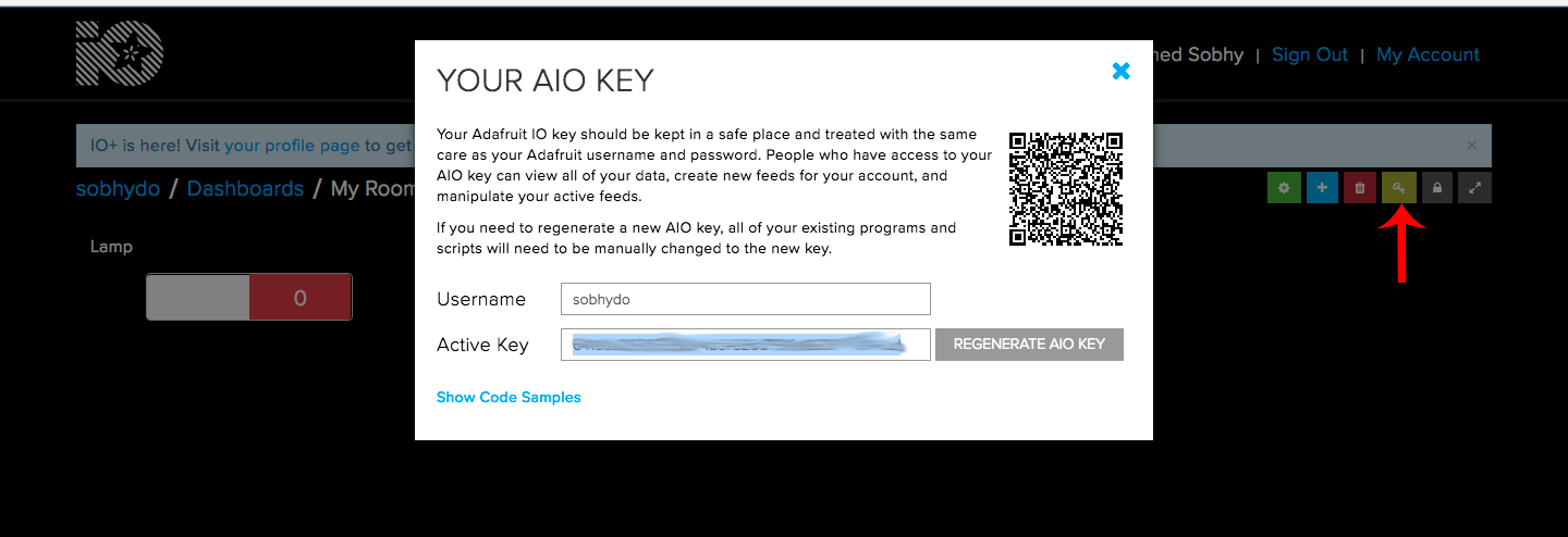
#define WIFI_SSID "<Your Wifi SSID>"
#define WIFI_PASS "<Your WiFi Password>"

#define MQTT_SERV "io.adafruit.com"
#define MQTT_PORT 1883
#define MQTT_NAME "<Your Adafruit IO Username>"
#define MQTT_PASS "<Your Adafruit IO Key>"
These are the settings for connecting to your Adafruit IO Account. Your Adafruit IO Key is a string of characters that can be found by pressing the gold key button on your dashboard, or “View AIO Key” on the left-hand menu of Adafruit IO.
Next, create WiFiClient and Adafruit_MQTT_Client objects as global variables, and instantiate the feed for your light switch:
WiFiClient client;
Adafruit_MQTT_Client mqtt(&client, MQTT_SERV, MQTT_PORT, MQTT_NAME, MQTT_PASS);

Adafruit_MQTT_Subscribe Lamp1 = Adafruit_MQTT_Subscribe(&mqtt, AIO_USERNAME"/feeds/Lamp");
Now, in the setup, we’ll connect to the WiFi and the MQTT server:
// Setup a feed called 'Lamp' for subscribing to changes.

Adafruit_MQTT_Subscribe Lamp1 = Adafruit_MQTT_Subscribe(&mqtt, AIO_USERNAME"/feeds/Lamp");

void MQTT_connect();

void setup() {
Serial.begin(115200);

pinMode(Relay1, OUTPUT);

// Connect to WiFi access point.
Serial.println(); Serial.println();
Serial.print("Connecting to ");
Serial.println(WLAN_SSID);

WiFi.begin(WLAN_SSID, WLAN_PASS);
while (WiFi.status() != WL_CONNECTED) {
delay(500);
Serial.print(".");
}
Serial.println();

Serial.println("WiFi connected");
Serial.println("IP address: ");
Serial.println(WiFi.localIP());

// Setup MQTT subscription for onoff feed.
mqtt.subscribe(&Lamp1);

}
This will connect you to WiFi and the MQTT server, and subscribe to the Lamp topic. We also set the Relay to be an output.
Now, in the main loop, we need to check to see if our subscription has been updated, and act accordingly. We’ll also occasionally ping the server to make sure we stay connected.
void loop() {

MQTT_connect();

Adafruit_MQTT_Subscribe *subscription;
while ((subscription = mqtt.readSubscription(20000))) {
if (subscription == &Lamp1) {
Serial.print(F("Got: "));
Serial.println((char *)Lamp1.lastread);
int Lamp1_State = atoi((char *)Lamp1.lastread);
digitalWrite(Relay1, Lamp1_State);

}
}
Finally, add the MQTT_connect function, which was part of one of the Adafruit_MQTT examples:
/***************************************************
Adafruit MQTT Library ESP8266 Example
Must use ESP8266 Arduino from:  https://github.com/esp8266/Arduino
Works great with Adafruit's Huzzah ESP board & Feather
 ---->   https://github.com/esp8266/Arduino
 ---->   https://github.com/esp8266/Arduino
Adafruit invests time and resources providing this open source code,
please support Adafruit and open-source hardware by purchasing
products from Adafruit!
Written by Tony DiCola for Adafruit Industries.
MIT license, all text above must be included in any redistribution
****************************************************/
void MQTT_connect()
{
  int8_t ret;
  // Stop if already connected
  if (mqtt.connected())
  {
    return;
  }

  Serial.print("Connecting to MQTT... ");
  uint8_t retries = 3;
  while ((ret = mqtt.connect()) != 0) // connect will return 0 for connected
  {
    Serial.println(mqtt.connectErrorString(ret));
    Serial.println("Retrying MQTT connection in 5 seconds...");
    mqtt.disconnect();
    delay(5000);  // wait 5 seconds
    retries--;
    if (retries == 0)
    {
      // basically die and wait for WDT to reset me
      while (1);
    }
  }
  Serial.println("MQTT Connected!");
}
And that should be it! Load it onto your device, start up the serial monitor, and flip the switch in your dashboard a few times to make sure that it’s connected! Now, we just need to connect it to our Google Assistant.

3- Connecting to Google Assistant Through IFTTT

Now we’ll connect our Google Assistant to the Adafruit IO MQTT Broker to allow us to control the lights with voice commands. To do this, we’ll use the IFTTT (If This Then That) platform, which allows hundreds of different services to trigger actions in a variety of other services.
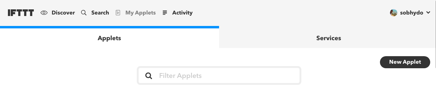
After you’ve set up your account and taken a look around, Select “My Applets” from the left hand menu, then click the blue “New Applet” button. This will take you to the applet editor, where you choose triggers (“If This”) and the subsequent actions (“Then That”).
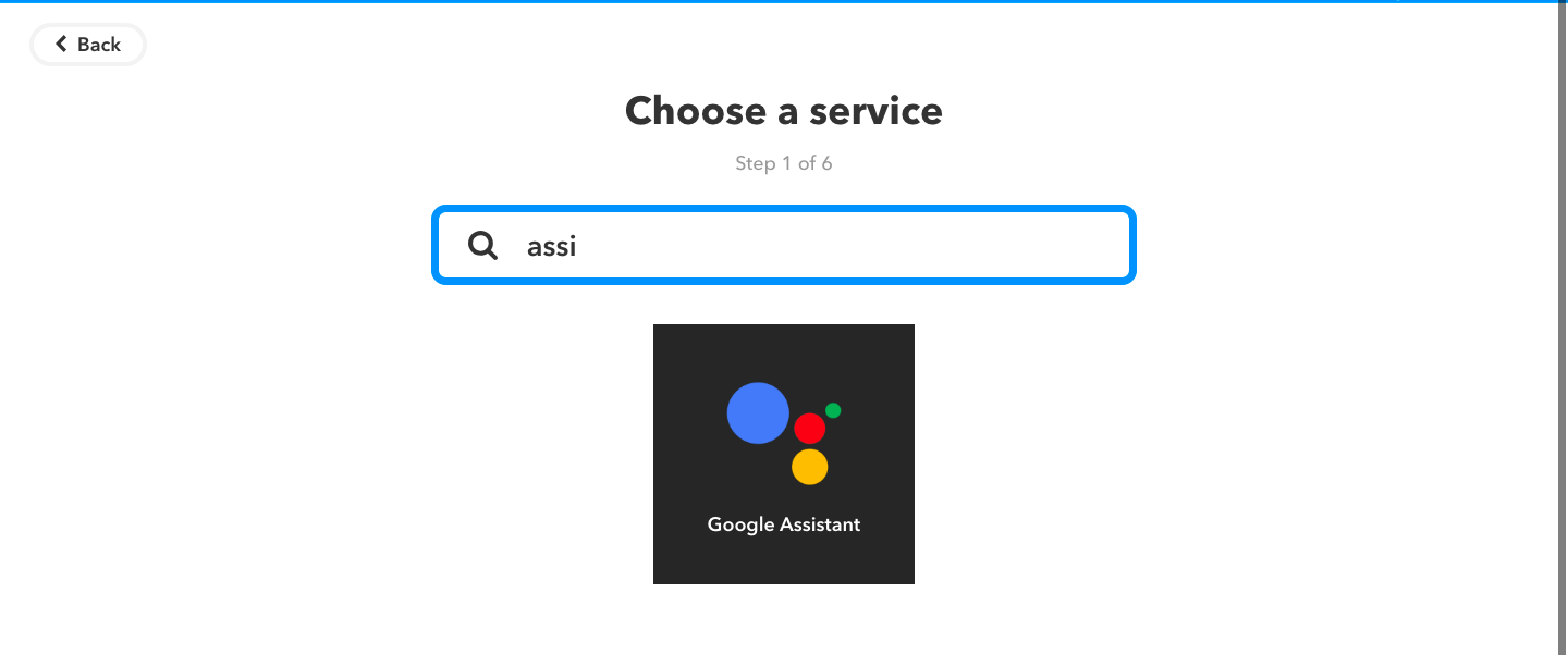

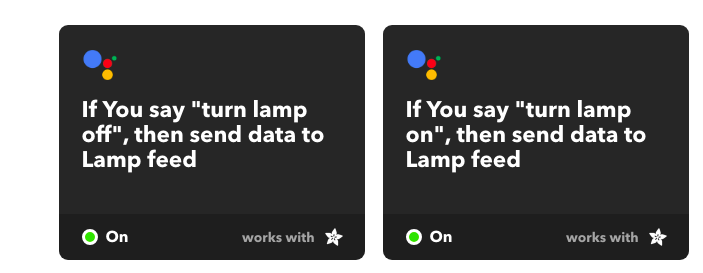
For your trigger, choose “Google Assistant” as the service then select “Say a simple phrase” from the menu of specific triggers.
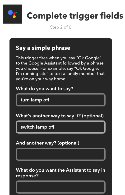
This will bring up a new list of fields to fill in, including variations of the activation phrase, the Google Assistant’s response, and the language. For my activation phrases, I chose “Turn lamp off” and “Switch lamp off” and you can add “Turn off lamp” too then click Next and Finish.

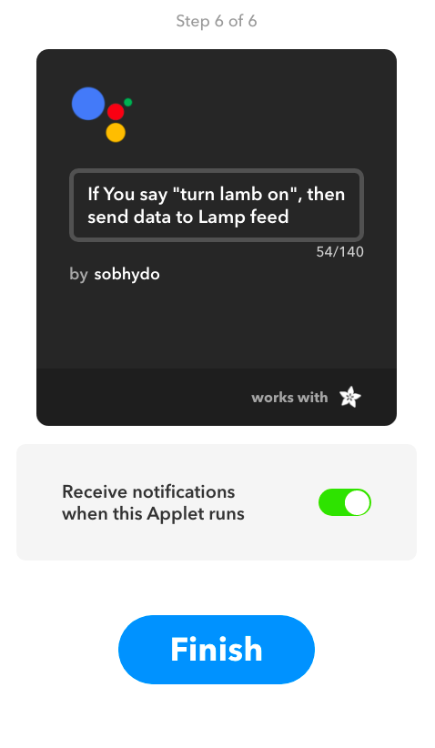
Your First Trig assigned to google assistant as you can see above .
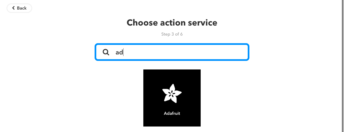

The final part of your applet is the Action, what your applet does in response to the Trigger. For the service, choose “Adafruit”, and for the specific Action, choose “Send data to Adafruit IO”.
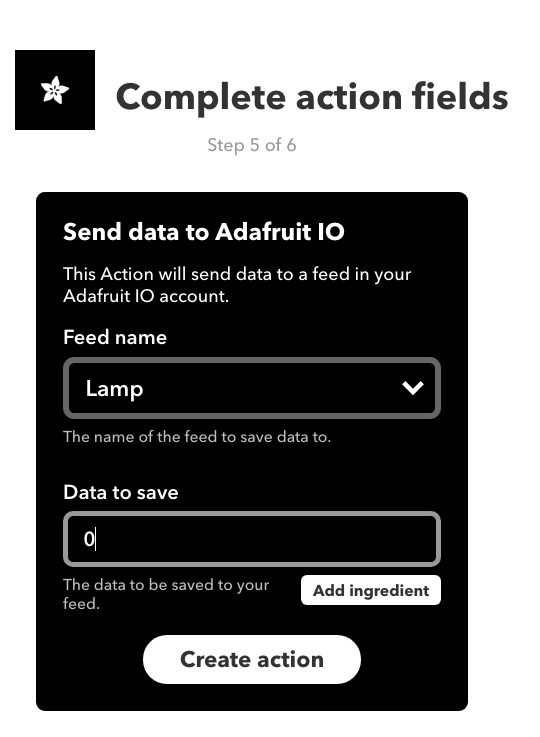
This will bring up two fields that you need to fill in. The first should be replaced with the name of the Adafruit IO feed you want to send data to, in this case “Lamp”. The second field is the data to send. For this applet, we’ll send “0” Zero, which is the string our ESP8266 is waiting for.
Once you have that applet finished, create a second one for turning the lights “ON”. You should now see two applets on your IFTTT Platform page. To activate them, go to the My Applets page on the main IFTTT site, click on the applet card, and click set the on-off toggle switch to “On”. If you haven’t already, IFTTT will ask to connect to your Adafruit IO and Google Assistant accounts. Allow the accounts to be linked, then turn on the second applet as well.
Once both applets are turned on, the setup should be complete! and you can control your
4- Hardware Setup
Once you finished all previous steps now you can control your relay as per connections indicated below

the following video made for the Action on google Demo and it summaries the full steps
I am getting a lot of errors for instance “AIO_USERNAME was not declared in this scope” I’m new to MQTT, tried putting my username in instead of AIO_USERNAME but message still the same? Do you have a code that works where I could just change wifi and AIO details? I have spent hours on this without success, any help would be much appreciated.
Thanks
Steve
Hello Steve 👋 can you please install required libraries before compiling the code as it looks you missed adafruit mqtt library